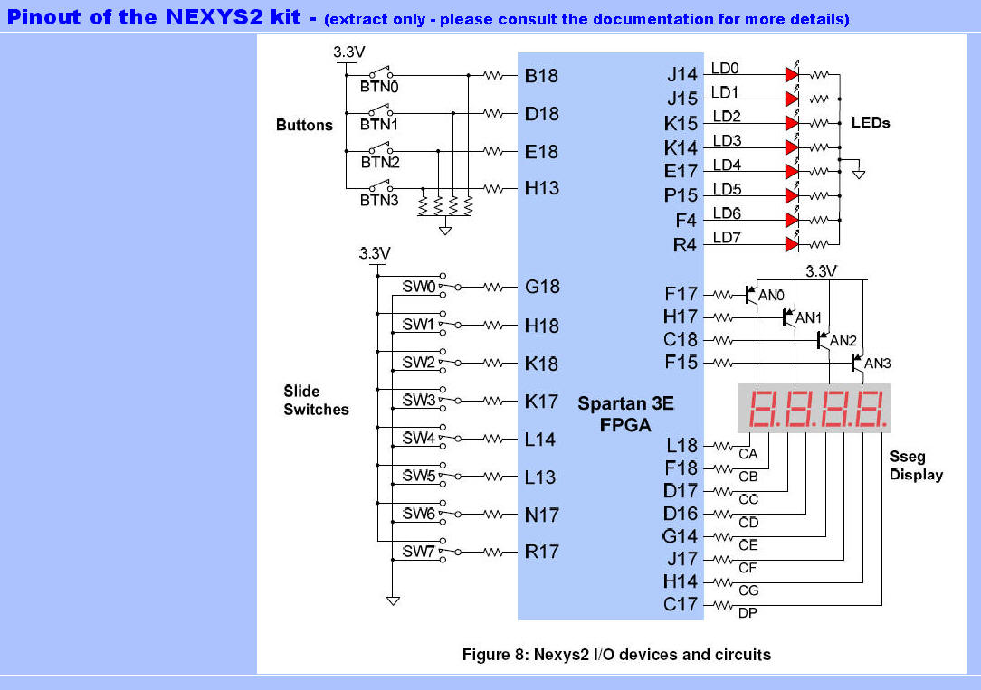
Seg(1) = Segment
a = CA
Seg(2) = Segment b = CB
Seg(3) = Segment c = CC
Seg(4) = Segment d = CD
Seg(5) = Segment e = CE
Seg(6) = Segment f = CF Seg(7) = Segment g = CG
Seg(8) = Segment dp = DP
Exercise - Test
the Kit
(1)
Create a schematic like below - it addresses
most of the inputs and outputs of the kit.
You will find the
components needed in the libraries Logic and
IO
Afterwards must
you create a UCF with the needed pins (BASYS
Pinout below)
Finally will you
be able to download the bit-file and the
test at the hardware.
(2)
Create a VHDL alternative to the test from above