Home ] Up ] Async. vs. Sync ] State Diagrams ] VHDL implementaions ] [ Levels of abstraction ] Kiss to FSM ]
Levels of abstraction

Up ] RTL Design ] FSM Design ] ASM Design ] Ad hoc Design ]

Return to DIG #10

The Task:

Create a sequential circuit which detect two input signals A and B and controls a signal Z

B=0 => If A have the same value 0/1 in two subsequent clock cycles must the output signal Z go high and stay high as long as A is stable.

B=1 => If the signal B is high must the output the output Z remain high whenever A detected equal in two subsequent clock cycles.


State Tables versus State Diagrams

The design of a State / Output table not a trivial task and can be compared with the task of writing a program (C++, Java etc.)

There might be many different but correct solutions to a task.

Normally will the solution with the fewest state be preferable, but its your choice.

By the selection of useful state names can you make the solution "understandable" for others.

   
The alternative to State / Output tables called State Diagrams.

Many designers prefer to draw this first and perhaps later create the table above.


In the classic digital design (before VHDL and FPGA's) was it important to optimize the design.

By selection of the "best" state-coding could a few gates and or Flip/Flops be saved.


Please note - A lesson to be learned:

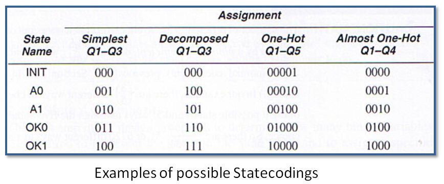
The One-Hot coding style will use as many Flip/Flops as the number of states - in comparison will a Binary, Gray, Decomposed only take |Log2(N)+1| Flip/Flops.

If you want 32 states will it take 32 F/F's with One-Hot but only 5 F/F's with a Binary coding.

Nevertheless will the synthesize-tool prefer a One-Hot coding if your synthesizing for a FPGA family and Binary coding if your planning to use a CPLD family.

The explanation of this fact:

FPGA's got lots of F/F's but less logic hence will a One-Hot coding be preferred  for "large" State Machines
CPLD's got fewer number of F/F's but lots of logic and hence will a Binary coding be preferred.