Operational Amplifier -
Link here
|
| |
Topics: |
Last updated:
21-03-11 |
|
The Operational amplifier based at a
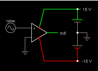
rather complicated Integrated Circuit. The Basic OpAmp got two input
terninals and one output
Please note that the powersupply seldom drawn in diagrams - and a
OpAmp will typically be have both a +15 Volt and - 15 Volt supply.
The center of the Powersupply called Ground and must be used for the
Connection of signals.
|
|
|
 |
 |
| |
|
| |
|
|
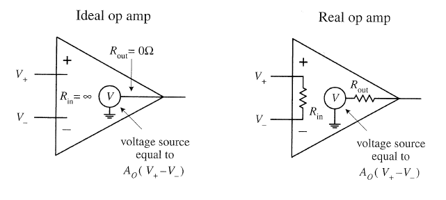
In an Ideal Op Amp
will the Amplification A0 be ?
Which value for A0 could be expected for a Real Op Amp ?
(like the one in the Circuit simulator)
|
| |
|
|
|
PEFI page 540 + 541 |
| x |
x |
 |
|
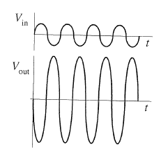
Can you explain why the sinus input curve gives the
square-like output?
|
|
 |
|
Can you calculate the A0 amplification of the Op Amp
above.
|
|
|
|
PEFI page 542 |
|
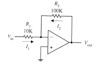
How much will the
input signal be Amplified?
Vout = Gain * Vin
What the advantage of
this circuit?
|
 |
|
|
PEFI page 543 |
 |
 |
|
What the common name
of this Op Amp circuit ?
What relation between Vout and Vin ?
|
Please not the Vout versus Vin
example as well. |
| |
|
|
|
PEFI page 543 |
 |
 |
|
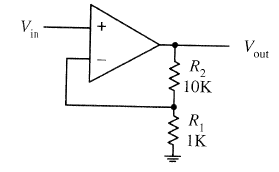
What the common name
of this Op Amp circuit ?
What the relation between Vout and Vin ?
|
|
| |
|
|
|
|
|
|
|
|
|
|
|
|
|
|
|
|
|
|
|
|
|
|
