Home ] Up ] [ SPI Slave ] Blok1 (internal comp) ] FPGA Main1 ] Testbench ]
SPI Slave

Up ]


Last updated: 23-03-11

Most Microcontrollers (like the the AVR) comes with a SPI interface which most likely should act as Master a SPI connection.

The SS (Slave Select) will be used to start a data-exchange between Master and Slave - The SS is active low which means that a transition from 1 to 0 indicates the start. Most likely will there be separate instructions / functions to control the Slave Select output from the Master (micro controller)

Data will be transfed to/from the Slave in terms of bytes - depending on the actual protokol (your choiche)

In order to make a general interface for data-exchange inside the FPGA will this Slave present how a Bidirctional DataBus together with an Address-bus and a Write Enable could be useful. 


bulletThis expample of a SPI implementation based at the following Ideas:
bullet 
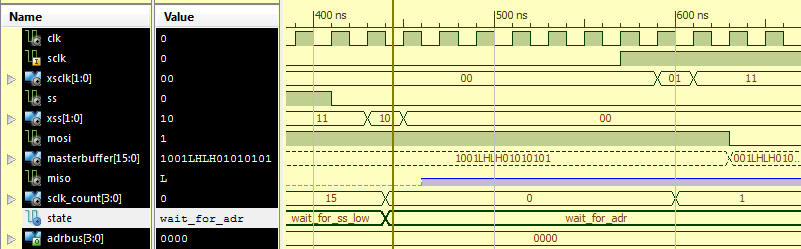
Each transmission from the Master start with a change @ SS from 1 to 0 (SS must stay low during the transmission)
bullet The Master will always transmit two bytes (16-bit)
bullet 
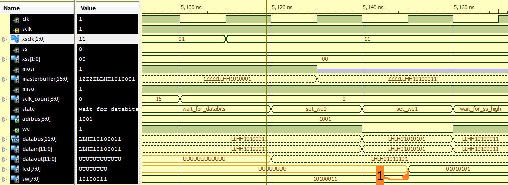
The first 4-bits will be the Address for the internal Blok (in this example will the blok have the Address = "1001"
bullet When the Slave have recieved the Address will it be transfered to the internal AdrBus.
bullet If its possible to read data (12-bits) from the Blok should it drive the DataBus with these data now.
bullet The 12-bit Data will be transfered to the from the DataBus to Udbuf in the "Load_UdBuf" state.
bullet In the Next 12 SClk cycles will the Content of the UdBuf be transfed to the Master while the InBuf will be filled with data from the Master
bulletAfter to InBuf being filled with data from the Master will the WE go low in order to enable the Blok to get data from the DataBus.
This means that the Slave will drive the DataBus while WE=0 and the selected Blok will go 3. State in order to allow this
.


In order to detect rising and falling edge at SS and SClk are two shiftregisters (of 2-bit) used.
"00" = Steady 0,   "01"= Rising edge,     "11"=Steady 1,    "10"= Falling edge
Hence will it be possible to let a Falling edge @ SS reset the SClk_Count
and a Rising edge @ SClk will increment the SClk_Count.

MISO                        <=  UdBuf( SClk_Cnt);   
InBuf( SClk_Cnt)  <=  MOSI;


Simulation of the Wait_for_databits => Set_we_0 => Set_we_1 => Wait_for_SS_high transitions


Example of the Blok1 - Component