Light Sensor
and Dimmer relay (Skumringsrelæ)
|
| |
|
Last updated:
05-03-12 |
|
The purpose of this example is to present:
-
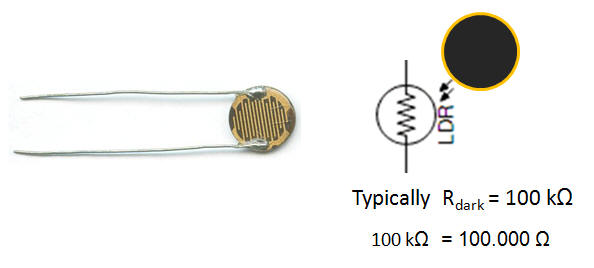
A LDR (Light
Dependent Resistor) which changes it resistance due
to the light-condition
-
A Voltage divider
formed by at LDR and a "fixed" resistor will give an
output voltage which depend on the LDR (mostly)
-
A BJT (Bipolar
Junction Transistor) will make it possible to
control the relative large current which needed to
turn on a LED and a relay as well.
-
A relay will utilize
a coil (and hence a magnet-field) to control
mechanical contacts.
-
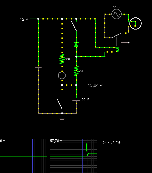
The Energy stored in
the coil will give very high voltages, when ever
it's turned off. In order to avoid this must a diode
be connected in reverse.
|
|
|
|

|
|
L |
|
|
 |
The
LDR resistor |
|
| . |
. |
 |
 |
| |
|
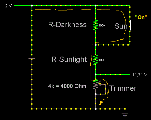
 | The simulator of
Falstad.com/Circuit dosen't offer a LDR
and hence must it be build with the
existing components.
 | The
LDR resistor formed of
two resistors:
One which gives the
Resistance when exposed
to darkness and one
which gives the
resistance when exposed
to light. |
 | The
"Sun" switch makes it
possible to turn the
light on and off. |
|
|
| |
|
 |
 |
| |
|
|
 |
The
Voltage divider |
|
| |
|
|
A voltage divider
usually formed by two resistors in series, hence will
Vout be given by:
Vout = Vin * ( R.trimmer / (R.trimmer + R.LDR)
Which circuit will be the Thevenin equivalent of the
voltage divider ?
|
| . |
. |
 |
 |
| |
|
|
 |
BJT - Bipolar Junction Transistor |
|
|
|
 |
How to use a Diode for circuit protection |
|
|
|
 |
How to use a Capacitor for circuit
protection |
|
| . |
. |
 |
|
| |
|
|
|